Introduction In order to adapt to the rapid detection, adjustment and repair of pressure sensors, this article determines the tested items according to a certain type of pressure sensor, and focuses on analyzing the measured parameters. It adopts Advantech IPC-610H industrial control computer and TESCOMER3000 electronic pressure controller design scheme. The software uses LabVIEW to complete development such as editing, compiling, linking, and debugging. The test data is automatically formed into a report, automatically stored and available for review, and the test record is exported in Excel format for convenient storage and printing.
1 overall design ideas This tester has strong specificity, and has high requirements on reliability and safety. The tester controls the gas circuit to simulate the water pressure environment. The pressure signal is generated by the pressure change to generate the corresponding response signal. The comparison of the specification data yields corresponding test results and displays the results on a liquid crystal display. The block diagram is shown in Figure 1.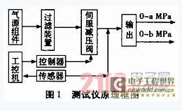
1.1 IPC IPC uses Advantech IPC-610H. The chassis is made of all-steel 19-inch 4U standard. The backplane is a 14-slot industrial-standard passive backplane PCA-6114P4-C. The power supply uses the 250-W industry-standard power supply PS-250ATX-ZE. PCA-6010V supports dual-channel DDR2667 SDRAM, up to 4GB, G2 version supports CF slot and DVI interface; conforms to PICMG1.0 standard, supports LGA775IntelCore2DuoFSB1066MHz processor, supports dual-channel DDR2667SDRAM, up to 4GB single GbELANviaPCIexl channel COM port, 4 SATA ports, 8 USB ports.
1.2 High-power relay card High-power relay card Select ADLINK PCI-7260, the board contains eight relay output channels, each channel can switch 5A250V AC power supply, or 5A30V DC power supply, the panel is pluggable The connector also features high current switching and easy wiring. ADLINK PCI-7260 provides eight independent digital input channels, and filter circuits are designed for these digital input channels to filter possible signal surges and improve system reliability.
1.3 A/D card A/D card selects PIS0-81312 bit isolated A/D card. PIS0-813 has 32 single-ended input analog channels. The isolation voltage of PIS0-813 is up to 3000V. This card is the most economical PCI bus A/D card. It comes with a 37-pin D-type connector for 5V PCI bus slots and supports true plug-and-play. PCI Bus Analog Output Card High-resolution multi-channel analog output card, simple without jumper design, software calibration.
1.4 Electronic pressure controller The electronic pressure controller of TESCOMER3000 makes the outlet pressure of the pressure regulating valve stable and accurate, and the adjustment speed is fast and the response speed is fast. The ER3000 can be controlled by PLC or computer software. People do not have to arrive at the site to achieve remote control. Explosion-proof design enables the operator to stay away from danger and the process of output air control can be controlled.
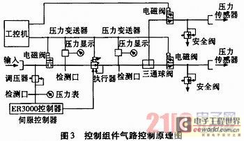
2 Main structure and brief working principle of the gas source module The gas source module is an energy storage gas source composed of a high-pressure gas cylinder, a one-way valve, a high pressure filter and a valve. The input of this component is connected to the high-pressure gas pipeline, and the output end is connected to the control cabinet with a high-pressure hose. High-pressure gas cylinders mainly play a role of energy storage to meet the needs of the system gas; the role of the filter is mainly to filter out particles, oil and other impurities, to meet the dew point and cleanliness requirements. Pipes use 1/4-inch stainless steel pipe to meet the strength requirements of the trachea. The entire device is housed in the cabinet. Air control diagram shown in Figure 2.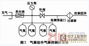 The control module is the core of the system. Its main function is to use program control to control the gas pressure output in different channels. At the same time, it has undervoltage alarm and overvoltage protection, program pressure regulation, fault alarm function. The intake control valve uses a two-position two-way solenoid valve. The program controls the solenoid valve to switch the pipeline. The system uses American TESCOM high-precision air drive servo pressure reducing valve, pressure sensor and controller to automatically adjust and adjust according to the set pressure. The pressure controller uses TESCOM's ER3000 electronic pressure controller. The controller and the corresponding control valve can meet the pressure control range of 0 ~ 10MPa. The pressure sensor uses 100 series sensors matched by TESCOM. The working pressure ranges from 0 to 1000 psi with an accuracy of 0.25, the output signal is 4 to 20 mA, and the operating voltage is 24 VDC. The output passages are all equipped with solenoid valve emptying control. Taking into account the simplicity of the pipeline, the output solenoid valve and the discharge solenoid valve are combined, using a DCF6 type two-position three-way solenoid valve. The main pipe uses 1/4 inch stainless steel pipe. For safety, a safety valve is installed on each pressure branch. Air control of the control module is shown in Figure 3.
3 software design The system software platform for LabVIEW, has a good man-machine interface, divided into system login, sensor testing, save reports, parameter settings, maintenance systems, online help seven modules, the test interface shown in Figure 4.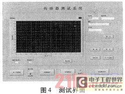
3.1 Parameter settings require administrator rights, click on the parameter settings; enter the administrator's operation password, enter the settings interface; you can change the eligibility criteria, test time, add management operators, modify the save and exit to perform other operations .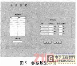
3.2 Inspection System This function is mainly used to manually adjust the output pressure and detect the external device or device self-test. The operation request has the administrator authority; click on the system self-test, enter the administrator's operation password, enter the maintenance system interface; click on the input solenoid valve, enter the solenoid valve action, the panel input light is on, check the input solenoid valve action is normal, input pressure display Whether it is normal; click the sensor output solenoid valve, the signal output solenoid valve can respectively detect the corresponding solenoid valve action is normal; rotation output pressure adjustment or input pressure value to be adjusted, can achieve manual pressure adjustment output; use is complete, click to exit Key, you can go back to the initial interface and perform other operations.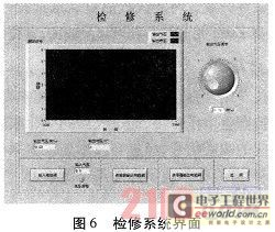
4 Conclusion This tester completes a series of underwater pressure sensor testing, the system hardware fully considers the reliability, real-time and safety of the measurement process. The system software fully considers the normative design of the algorithm and the friendly interface of the human-computer interaction interface. . After actual use, it meets the test requirements.
1 overall design ideas This tester has strong specificity, and has high requirements on reliability and safety. The tester controls the gas circuit to simulate the water pressure environment. The pressure signal is generated by the pressure change to generate the corresponding response signal. The comparison of the specification data yields corresponding test results and displays the results on a liquid crystal display. The block diagram is shown in Figure 1.

1.1 IPC IPC uses Advantech IPC-610H. The chassis is made of all-steel 19-inch 4U standard. The backplane is a 14-slot industrial-standard passive backplane PCA-6114P4-C. The power supply uses the 250-W industry-standard power supply PS-250ATX-ZE. PCA-6010V supports dual-channel DDR2667 SDRAM, up to 4GB, G2 version supports CF slot and DVI interface; conforms to PICMG1.0 standard, supports LGA775IntelCore2DuoFSB1066MHz processor, supports dual-channel DDR2667SDRAM, up to 4GB single GbELANviaPCIexl channel COM port, 4 SATA ports, 8 USB ports.
1.2 High-power relay card High-power relay card Select ADLINK PCI-7260, the board contains eight relay output channels, each channel can switch 5A250V AC power supply, or 5A30V DC power supply, the panel is pluggable The connector also features high current switching and easy wiring. ADLINK PCI-7260 provides eight independent digital input channels, and filter circuits are designed for these digital input channels to filter possible signal surges and improve system reliability.
1.3 A/D card A/D card selects PIS0-81312 bit isolated A/D card. PIS0-813 has 32 single-ended input analog channels. The isolation voltage of PIS0-813 is up to 3000V. This card is the most economical PCI bus A/D card. It comes with a 37-pin D-type connector for 5V PCI bus slots and supports true plug-and-play. PCI Bus Analog Output Card High-resolution multi-channel analog output card, simple without jumper design, software calibration.
1.4 Electronic pressure controller The electronic pressure controller of TESCOMER3000 makes the outlet pressure of the pressure regulating valve stable and accurate, and the adjustment speed is fast and the response speed is fast. The ER3000 can be controlled by PLC or computer software. People do not have to arrive at the site to achieve remote control. Explosion-proof design enables the operator to stay away from danger and the process of output air control can be controlled.
2 Main structure and brief working principle of the gas source module The gas source module is an energy storage gas source composed of a high-pressure gas cylinder, a one-way valve, a high pressure filter and a valve. The input of this component is connected to the high-pressure gas pipeline, and the output end is connected to the control cabinet with a high-pressure hose. High-pressure gas cylinders mainly play a role of energy storage to meet the needs of the system gas; the role of the filter is mainly to filter out particles, oil and other impurities, to meet the dew point and cleanliness requirements. Pipes use 1/4-inch stainless steel pipe to meet the strength requirements of the trachea. The entire device is housed in the cabinet. Air control diagram shown in Figure 2.


3 software design The system software platform for LabVIEW, has a good man-machine interface, divided into system login, sensor testing, save reports, parameter settings, maintenance systems, online help seven modules, the test interface shown in Figure 4.

3.1 Parameter settings require administrator rights, click on the parameter settings; enter the administrator's operation password, enter the settings interface; you can change the eligibility criteria, test time, add management operators, modify the save and exit to perform other operations .

3.2 Inspection System This function is mainly used to manually adjust the output pressure and detect the external device or device self-test. The operation request has the administrator authority; click on the system self-test, enter the administrator's operation password, enter the maintenance system interface; click on the input solenoid valve, enter the solenoid valve action, the panel input light is on, check the input solenoid valve action is normal, input pressure display Whether it is normal; click the sensor output solenoid valve, the signal output solenoid valve can respectively detect the corresponding solenoid valve action is normal; rotation output pressure adjustment or input pressure value to be adjusted, can achieve manual pressure adjustment output; use is complete, click to exit Key, you can go back to the initial interface and perform other operations.

4 Conclusion This tester completes a series of underwater pressure sensor testing, the system hardware fully considers the reliability, real-time and safety of the measurement process. The system software fully considers the normative design of the algorithm and the friendly interface of the human-computer interaction interface. . After actual use, it meets the test requirements.
Tactical Backpack,Tactical Backpack Outdoor,Tactical Bag For Hunting,Men Backpacks
Guangzhou Miaozhun Jie Trade Co.,Ltd. , https://www.focuhunter.shop