1 Types and advantages and disadvantages of flow measuring instruments
Up to now, there are as many as 60 types of flow meters available for industrial use. The reason for so many varieties is that no flow test instrument has been found that can be applied to any fluid type, any range, any flow conditions, and any conditions of use. Each of these flow meters has its specific scope of application and its limitations.
The flow measuring instrument is divided into mechanical principle, thermal principle, acoustic principle, electrical principle, optical principle and atomic physics principle according to the measurement principle. According to the current zui popular, Zui extensive classification, can be divided into: differential pressure flowmeter, volumetric flowmeter, float flowmeter, turbine flowmeter, electromagnetic flowmeter, fluid vibration flowmeter, ultrasonic flowmeter, mass flow Meter and open channel flowmeter. The advantages and disadvantages of various flowmeters and the main application areas are shown in Table 1. (Because of the variety of mass flowmeters, the advantages and disadvantages of each other and the scope of application are different, so it is not listed in the table):

(The similarity of the viscous effect in fluid mechanics is denoted as Re.Re=ÏvL/μ, Ï, μ are the fluid density and viscosity, v, L is the characteristic velocity of the flow field and the characteristic length Reynolds number is small, meaning fluid flow The viscous force between the various mass points is dominant, and the fluid particles flow regularly parallel to the inner wall of the pipeline, which is a laminar flow state. The large Reynolds number means that the inertial force is dominant and the fluid is in a turbulent flow state.
2 electromagnetic flowmeter measurement principle
According to Faraday's law of electromagnetic induction, when a conductor moves in a magnetic field to cut a magnetic line of force, an induced electromotive force e is generated at both ends of the conductor, the direction of which is determined by the right-hand rule, the magnitude and magnetic induction of the magnetic field B, and the conductor is within the magnetic field. The effective length L and the conductor are proportional to the velocity u of the magnetic field. If B, L, and u are perpendicular to each other, then: e=BLu
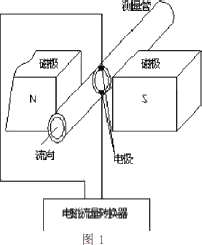
Similarly, if a non-magnetic tube with an inner diameter D is placed perpendicular to the direction of the magnetic field in a uniform magnetic field of magnetic induction B, the conductive liquid cuts the magnetic field lines when the conductive liquid moves at the flow velocity u in the tube. A pair of electrodes are mounted on both sides of the diameter of the pipe perpendicular to the diameter of the magnetic field (as shown in Figure 1).

It can be proved that as long as the flow velocity distribution in the pipe is symmetrically distributed with the axis, an induced electromotive force will be generated between the two electrodes:
e=kBDÅ«
Where Å« is the average flow velocity (m/s) on the cross section of the pipe; k is a constant coefficient, dimensionless; D is the diameter of the measuring tube (m); B is the magnetic induction (T). This gives the volume flow through the pipe:

It can be seen from the above formula that when the measuring tube structure is constant, the volume flow rate qv is proportional to the ratio e/B, and regardless of the state of the fluid and the physical property parameter, the volume ratio value qv can be obtained by measuring the ratio e/B. When the magnetic induction B is a constant value, the volume flow rate qv is proportional to the induced electromotive force e.
B is the magnetic induction of a DC magnetic field or a sinusoidal alternating magnetic field or other type of magnetic field. It is provided by the excitation system of the electromagnetic flowmeter. The excitation system can provide various forms of magnetic field waveforms to the electromagnetic flow sensor. Different magnetic field waveforms directly determine the characteristics of the working magnetic field of the electromagnetic flow sensor, and basically determine the processing method of the electromagnetic flowmeter flow signal, which has a great influence on the working performance of the electromagnetic flowmeter.
3 electromagnetic flowmeter field application data and analysis
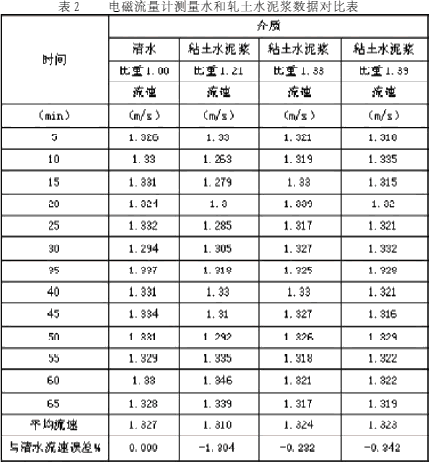
An on-site test of the flow rate of the clay grout by the electromagnetic flowmeter was carried out at the ground pre-grouting site of the Fengshijing coal mine of Zhujixi Coal Mine of Weibei Coal and Electricity Group. The clean water and three proportions of clay cement slurry were tested separately during the test. The specific gravity of the clean water is 1.00 g/cm3, and the grout specific gravity of the three clay grouts is 1.21 g/cm3, 1.33 g/cm3, and 1.39 g/cm3, respectively. Since the electromagnetic flowmeter measures the flow of clean water, the technology is very mature. Therefore, the flow rate of the clean water is measured by the electromagnetic flowmeter as the standard data during the test. The data of the clay cement slurry is compared with it to determine the accuracy of the measurement. . The amount of grouting pump selected during the test was 99 L/min; the grouting line was open without pressure during the test; the test time was 65 min, and the sampling interval was 5 min. The specific test data is shown in Table 2.

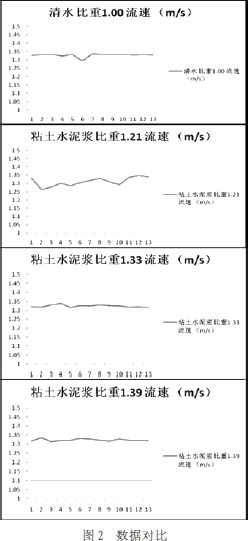
The comparison curve of the four sets of data is shown in Figure 2.

The experimental data showed that the average instantaneous flow rate of clean water was 1.327m/s, and the average instantaneous flow rate of clay cement with specific gravity of 1.21g/cm3 was 1.31m/s; the average instantaneous flow rate of clay cement with specific gravity of 1.33g/cm3 was 1.324m. /s; The average instantaneous flow rate of the clay cement with a specific gravity of 1.39 g/cm3 is 1.323 m/s, and the average instantaneous flow velocity error with the clear water is between -0.232% and -1.304%.
4 Conclusion
After field test, in the test range, the error of the clay cement slurry flow and the clean water flow measured by the electromagnetic flowmeter is not more than 1.4%, which is in line with the practical application requirements of the field engineering. In the case of a pump volume of 99L / Table 2 electromagnetic flowmeter measurement water and rolling cement slurry data comparison table min can replace the current manual measurement. To further improve the accuracy of the measurement, it can be recalibrated before the measurement, or increase the loss factor by about 1% during the measurement. Because the measurement in engineering construction is very different from the test measurement in the laboratory, the measurement accuracy of the electromagnetic flowmeter in the field test can meet the needs of engineering construction. In order to ensure the accuracy of the measurement, the construction site should pay attention to ensure that the pipeline is full, and try to keep the measuring instrument away from the strong electromagnetic environment and avoid the equipment from violent vibration.
Cop Cars,Police Van,Motorbike For Cruiser,Motocross Road Bike
Jinan Maxview Industrial Co.,Ltd. , https://www.maxviewmoto.com