General
Particle contamination in process water accelerates the rate of wear of system components. The particles suspended in the media also have detrimental effects on ends products. In order to protect the operational infrastructure and to guarantee shorter maintenance times, it is essential to have a filtration system to remove solid particles from operating fluids.
The automatic back-flushing filter has been highly useful. Numerous operators of power stations, district heating, sewage treatment plants, and manufacturing plants have relied on this dependable filter for many years.
Structure
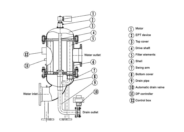
Operate principle
The fluid to be filtered flows through the filter elements of the back-flushing filter, passing from the inside to the outside. Contamination particles then collect on the inside of the filter elements.
As the level of contamination increases, the differential pressure between the contaminated and clean sides of the filter increases.
Back-flushing
1.The gear motor rotates the flushing arm under the filter elements and ensures the contamination is discharged.
2.The contamination is flushed away through the open back-flushing valve.
3.The pressure drop between filtrate side and back-flushing line flushes a small amount of the filtrate back through the contaminated filter elements.
4.The contamination particles collected on the inside of the filter elements are loosened and flushed into the backflushing line via the flushing arm.
5.After the "back-flushing time per element" has expired, the back-flushing valve is closed. In this way, all the filter elements are back-flushed, one after the other.
A back-flushing cycle is terminated once all filter elements have been cleaned.
Backwash Cartridge Filters Structure is triggered:
- When the differential pressure trigger point is exceeded,
- By means of an adjustable timer
- By pressing the TEST button.
Advantages Optimum structure and back-flushing design
The special conical shape and configuration of the filter elements allow consistent flow, resulting in a low pressure drop and complete cleaning of the elements.
Very low-maintenance. Its robust design, specially developed for retrofitting, makes installation in both existing and new systems fast and cost-effective.
Pulse-aided back-flushing
On the control types EPT and PT, the flushing arm remains under the filter element for only a few seconds.
Â
Variable filter isometry
The inlet and outlet flanges as well as the back-flushing line can be configured in different positions. This means that the filter can be integrated easily into any system layout.
Â
Electromechanical design
Simple install. PLC controller and drop pressure test pipes connected already, connect with air source can into use.
Â
Parameter settableÂ
Users can set drop pressure and time on actual usage.Â
Performance
High processing performance |
Flow rate up to 10,000 m3/h |
High throughput with compact dimensions |
Flow-optimized filter |
Maximum utilization of the filter area |
Isokinetic filtration and back-flushing |
| No interruption to operation | Continuous flow of filtrate even during back-flushing |
| Consistently high quality | Certified to ISO 9001 |
Unbeatable Δp curve |
Conical filter elements |
| Global Presence | Worldwide Service |
Long service life |
Components tried and tested in thousands of applications |
| Customized adaptation to the particular application | Numerous equipment options Individually adjustable control parameters |
| Additional dynamic element cleaning with low loss of flushing fluid |
Pulse-aided back-flushing |
Costs
Excellent price-performance ratio |
Extensive standard equipment for real-world applications |
Highly reliable |
Fully automatic operation |
Reduced costs due to simple and space-saving installation |
Variable housing isometry |
Simple installation and commissioning |
Ready-to-operate unit |
Maintenance Â
Â
Low maintenance costs |
Easy to service |
|
Guaranteed high quality filtrate Low maintenance |
Static seal between contaminated and clean side |
Applications
Power industry
• Conditioning of industrial waterused to cool generators
• Filtration of sealing water to increase the service lifeof the turbine shaft floating ring seals in hydroelectric power stations
Â
Steel industry
• Filtration of process water to protect nozzlesand pumps in high pressure descaling
• Water conditioning for coolingblast furnaces and rolling mills
• Emulsion filtration in hot and cold rolling mills
• Filtration of rolling emulsions
Â
Paper industry
• Protection of all types of nozzles
• on paper machines
• Treatment of fresh water (e.g. river water)to be used for cooling
Â
Automotive industry
• Filtration of coolant lubricants
• Filtration of washing fluids
• Protection of machine tools
Â
Marine
• Pre-filtration forballast water conditioning systems
Â
Chemical industry
• Cooling water filtration
• Waste water filtration
• Filtration of chemicals
Â
Oil and gas industry
• Filtration of injection water
• Filtration of cooling water
• Filtration of service water
• Filtration of flushing water (pipeline flushing)
• Filtration solution for the subsea sector
Â
Water / waste water conditioning
• Protective filter before membrane systems
• Conditioning of service water in sewage treatment plants
Â
Mining
• Filtration of water for shield spraying
• Filtration of water for coal-cutting machinery
• Treatment of cooling water for mine ventilation
Technical specifications
Â
| Maximum operating pressure | 6, 10 or 16 bar (size-dependent) |
Flow rate |
5T/H-7500T/H |
Filter degree |
80-3500um |
Operating temperature |
90 °C |
| Media | Low viscosity liquid, like:water, suspended liquid ≤60MM2/S |
| Drop pressure between outlet and drain | ≥1.5bar |
| Power supply | Electric or pneumatic |
Material of filter housing |
Carbon steel (Corrosion protection for carbon steel filter housing) or stainless steel |
| Material of filter elements | Stainless steel 316 |
| Material of internal parts | Stainless steel 304 |
Power supply
Electric or pneumatic:EPT
Electric: EU
Â
Power supply |
EPT |
EU |
| Motor | EU | EU |
Drain valve |
PT |
EU |
| DP gauge | EU | EU |
Position switch |
EU |
EU |
Control box |
EU |
EU |
How to select model
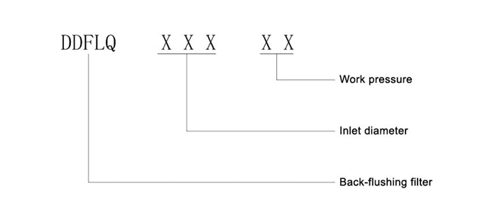
Â
| NO. | Â Item. | Â Model |
|||||||||||
|
 DDFLQ 100 |
 DDFLQ 125 |
 DDFLQ 200 |
 DDFLQ 250 |
 DDFLQ 300 |
 DDFLQ 350 |
 DDFLQ 400 |
 DDFLQ 500 |
 DDFLQ 600 |
 DDFLQ 700 |
 DDFLQ 800 |
 DDFLQ 900 |
||
| Â 1 | Inlet/outlet (DN) | Â 100 | 125Â | 200Â | 250 | 300Â | 350Â | 400Â | 500Â | 600Â | 700Â | 800Â | 900Â |
 2 |
Flow rate(T/H) | Â 100 | 100 | Â 200 | 400 | Â 500 | Â 800 | Â 1000 | Â 1500 | 2000 | 3000Â | 4000Â | 5000Â |
| Â 3 | Liquid speed(M/S) | Â 3.54 | Â 2.26 | Â 1.77 | 1.7Â | 1.96 | Â 2.31 | 2.21 | 2.12Â | 1.96Â | 2.17Â | 2.21Â | 2.18Â |
 4 |
Motor power(KW) | Â 0.55 | Â 0.55 | 0.55Â | 0.55Â | 0.55Â | 0.75Â | 0.75Â | 0.75Â | 1.1Â | 1.1Â | 1.1Â | 1.1Â |
| Â 5 | Drain drive power(KW) | Â 0.09 | Â 0.09 | 0.09Â | 0.09Â | 0.09 | Â 0.09 | 0.09Â | 0.09Â | 0.037Â | 0.037Â | 0.037Â | 0.037Â |
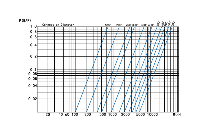
| Â 6 | Loss(Mpa) | Â 0.02-0.04 | |||||||||||
| Â 7 | Filter degree(um) | Â 80-3500 | |||||||||||
| Â 8 | DP(Mpa) | Â 0.01-0.15 | |||||||||||
 9 |
Back flushing time (S) | Â 0-180 | |||||||||||
| Â 10 | Motor rotating speed (R/MIN) | Â 0.75 | |||||||||||
| Â 11 | Operate | Â auto or manual | |||||||||||
Filter degree
Â
| Â um | Â 100 | Â 120 | Â 150 | Â 200 | Â 400 | Â 800 | 1500 | Â 3000 |
| Â Mesh number | Â 150 | Â 120 | Â 100 | Â 80 | Â 40 | Â 20 | 10 |
 5 |
Loss grid
Installation
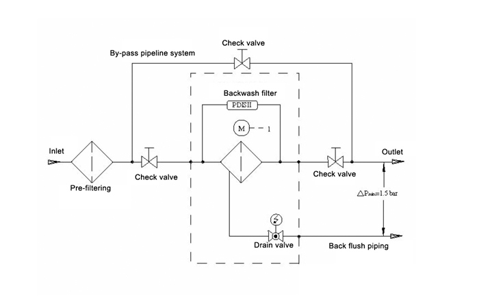
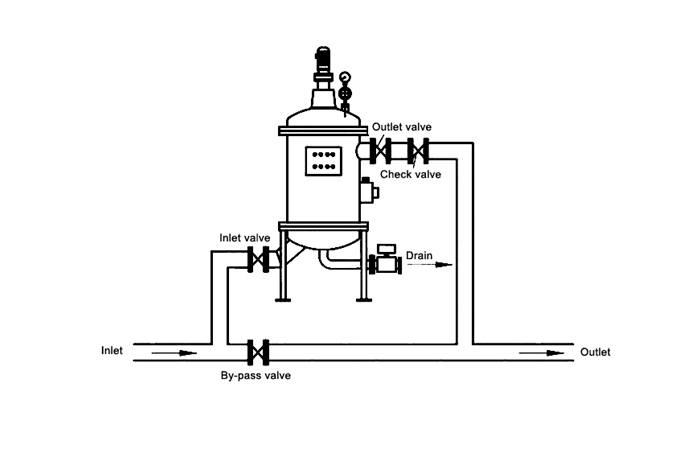
Vertical install, foundation bolts fixed. Filters can't be seen as pipeline strength support. Pipeline diameter not less than standard drain butterfly valve.
Supply compressed air: make sure air clean, 2bar≤pressure≤8bar, air connection:G1,4" ISO228
Â
Suggest pre-treating equipment before automatic back-flushing filter, aim to avoid impact from particles to filter.
| Automatic back-flushing filter | Pre-treating |
| Â <500um | 3mm |
| Â >500um | 10mm |
Spare parts
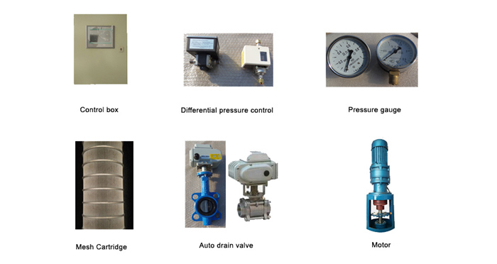
Â
General
Particle contamination in process water accelerates the rate of wear of system components. The particles suspended in the media also have detrimental effects on ends products. In order to protect the operational infrastructure and to guarantee shorter maintenance times, it is essential to have a filtration system to remove solid particles from operating fluids.
The automatic back-flushing filter has been highly useful. Numerous operators of power stations, district heating, sewage treatment plants, and manufacturing plants have relied on this dependable filter for many years.
Structure

Operate principle
The fluid to be filtered flows through the filter elements of the back-flushing filter, passing from the inside to the outside. Contamination particles then collect on the inside of the filter elements.
As the level of contamination increases, the differential pressure between the contaminated and clean sides of the filter increases.
Back-flushing
1.The gear motor rotates the flushing arm under the filter elements and ensures the contamination is discharged.
2.The contamination is flushed away through the open back-flushing valve.
3.The pressure drop between filtrate side and back-flushing line flushes a small amount of the filtrate back through the contaminated filter elements.
4.The contamination particles collected on the inside of the filter elements are loosened and flushed into the backflushing line via the flushing arm.
5.After the "back-flushing time per element" has expired, the back-flushing valve is closed. In this way, all the filter elements are back-flushed, one after the other.
A back-flushing cycle is terminated once all filter elements have been cleaned.
Backwash Cartridge Filters Structure is triggered:
- When the differential pressure trigger point is exceeded,
- By means of an adjustable timer
- By pressing the TEST button.
Advantages Optimum structure and back-flushing design
The special conical shape and configuration of the filter elements allow consistent flow, resulting in a low pressure drop and complete cleaning of the elements.
Very low-maintenance. Its robust design, specially developed for retrofitting, makes installation in both existing and new systems fast and cost-effective.
Pulse-aided back-flushing
On the control types EPT and PT, the flushing arm remains under the filter element for only a few seconds.
Â
Variable filter isometry
The inlet and outlet flanges as well as the back-flushing line can be configured in different positions. This means that the filter can be integrated easily into any system layout.
Â
Electromechanical design
Simple install. PLC controller and drop pressure test pipes connected already, connect with air source can into use.
Â
Parameter settableÂ
Users can set drop pressure and time on actual usage.Â
Performance
High processing performance |
Flow rate up to 10,000 m3/h |
High throughput with compact dimensions |
Flow-optimized filter |
Maximum utilization of the filter area |
Isokinetic filtration and back-flushing |
| No interruption to operation | Continuous flow of filtrate even during back-flushing |
| Consistently high quality | Certified to ISO 9001 |
Unbeatable Δp curve |
Conical filter elements |
| Global Presence | Worldwide Service |
Long service life |
Components tried and tested in thousands of applications |
| Customized adaptation to the particular application | Numerous equipment options Individually adjustable control parameters |
| Additional dynamic element cleaning with low loss of flushing fluid |
Pulse-aided back-flushing |
Costs
Excellent price-performance ratio |
Extensive standard equipment for real-world applications |
Highly reliable |
Fully automatic operation |
Reduced costs due to simple and space-saving installation |
Variable housing isometry |
Simple installation and commissioning |
Ready-to-operate unit |
Maintenance Â
Â
Low maintenance costs |
Easy to service |
|
Guaranteed high quality filtrate Low maintenance |
Static seal between contaminated and clean side |
Applications
Power industry
• Conditioning of industrial waterused to cool generators
• Filtration of sealing water to increase the service lifeof the turbine shaft floating ring seals in hydroelectric power stations
Â
Steel industry
• Filtration of process water to protect nozzlesand pumps in high pressure descaling
• Water conditioning for coolingblast furnaces and rolling mills
• Emulsion filtration in hot and cold rolling mills
• Filtration of rolling emulsions
Â
Paper industry
• Protection of all types of nozzles
• on paper machines
• Treatment of fresh water (e.g. river water)to be used for cooling
Â
Automotive industry
• Filtration of coolant lubricants
• Filtration of washing fluids
• Protection of machine tools
Â
Marine
• Pre-filtration forballast water conditioning systems
Â
Chemical industry
• Cooling water filtration
• Waste water filtration
• Filtration of chemicals
Â
Oil and gas industry
• Filtration of injection water
• Filtration of cooling water
• Filtration of service water
• Filtration of flushing water (pipeline flushing)
• Filtration solution for the subsea sector
Â
Water / waste water conditioning
• Protective filter before membrane systems
• Conditioning of service water in sewage treatment plants
Â
Mining
• Filtration of water for shield spraying
• Filtration of water for coal-cutting machinery
• Treatment of cooling water for mine ventilation
Technical specifications
Â
| Maximum operating pressure | 6, 10 or 16 bar (size-dependent) |
Flow rate |
5T/H-7500T/H |
Filter degree |
80-3500um |
Operating temperature |
90 °C |
| Media | Low viscosity liquid, like:water, suspended liquid ≤60MM2/S |
| Drop pressure between outlet and drain | ≥1.5bar |
| Power supply | Electric or pneumatic |
Material of filter housing |
Carbon steel (Corrosion protection for carbon steel filter housing) or stainless steel |
| Material of filter elements | Stainless steel 316 |
| Material of internal parts | Stainless steel 304 |
Power supply
Electric or pneumatic:EPT
Electric: EU
Â
Power supply |
EPT |
EU |
| Motor | EU | EU |
Drain valve |
PT |
EU |
| DP gauge | EU | EU |
Position switch |
EU |
EU |
Control box |
EU |
EU |
How to select model

Â
| NO. | Â Item. | Â Model |
|||||||||||
|
 DDFLQ 100 |
 DDFLQ 125 |
 DDFLQ 200 |
 DDFLQ 250 |
 DDFLQ 300 |
 DDFLQ 350 |
 DDFLQ 400 |
 DDFLQ 500 |
 DDFLQ 600 |
 DDFLQ 700 |
 DDFLQ 800 |
 DDFLQ 900 |
||
| Â 1 | Inlet/outlet (DN) | Â 100 | 125Â | 200Â | 250 | 300Â | 350Â | 400Â | 500Â | 600Â | 700Â | 800Â | 900Â |
 2 |
Flow rate(T/H) | Â 100 | 100 | Â 200 | 400 | Â 500 | Â 800 | Â 1000 | Â 1500 | 2000 | 3000Â | 4000Â | 5000Â |
| Â 3 | Liquid speed(M/S) | Â 3.54 | Â 2.26 | Â 1.77 | 1.7Â | 1.96 | Â 2.31 | 2.21 | 2.12Â | 1.96Â | 2.17Â | 2.21Â | 2.18Â |
 4 |
Motor power(KW) | Â 0.55 | Â 0.55 | 0.55Â | 0.55Â | 0.55Â | 0.75Â | 0.75Â | 0.75Â | 1.1Â | 1.1Â | 1.1Â | 1.1Â |
| Â 5 | Drain drive power(KW) | Â 0.09 | Â 0.09 | 0.09Â | 0.09Â | 0.09 | Â 0.09 | 0.09Â | 0.09Â | 0.037Â | 0.037Â | 0.037Â | 0.037Â |
| Â 6 | Loss(Mpa) | Â 0.02-0.04 | |||||||||||
| Â 7 | Filter degree(um) | Â 80-3500 | |||||||||||
| Â 8 | DP(Mpa) | Â 0.01-0.15 | |||||||||||
 9 |
Back flushing time (S) | Â 0-180 | |||||||||||
| Â 10 | Motor rotating speed (R/MIN) | Â 0.75 | |||||||||||
| Â 11 | Operate | Â auto or manual | |||||||||||
Filter degree
Â
| Â um | Â 100 | Â 120 | Â 150 | Â 200 | Â 400 | Â 800 | 1500 | Â 3000 |
| Â Mesh number | Â 150 | Â 120 | Â 100 | Â 80 | Â 40 | Â 20 | 10 |
 5 |
Loss grid

Installation
Vertical install, foundation bolts fixed. Filters can't be seen as pipeline strength support. Pipeline diameter not less than standard drain butterfly valve.
Supply compressed air: make sure air clean, 2bar≤pressure≤8bar, air connection:G1,4" ISO228

Â
Suggest pre-treating equipment before automatic back-flushing filter, aim to avoid impact from particles to filter.
| Automatic back-flushing filter | Pre-treating |
| Â <500um | 3mm |
| Â >500um | 10mm |

Spare parts

Â
Ignition Electrode,Ignition Spark Plug,Ignition Electrode for Gas BBQ
electronic ignition Co., Ltd. , http://www.skyeignition.com