The two gear shafts of the DA350-61 centrifugal compressor are placed in parallel on the horizontally split lower casing, and each gear shaft is supported by two bearings. The large gear shaft is a drive shaft, and the support bearings at both ends are round and horizontal bearing of the upper and lower halves, and the pinion shaft is a driven shaft, which forms a high speed rotor with the impeller. The rotor is supported by the tilting pad bearing, and the bearing hole diameter is ψ95 0.030. During operation, the main shaft is driven by the gear to drive the gear shafts on both sides to rotate, and the gas compression process is completed by the impeller and the diffuser. Maintaining a reasonable clearance between the shaft and the bearing bush is a prerequisite for the formation of a stable oil wedge by the formation of a liquid friction between the shaft and the bearing bush, accumulating and cooling the lubricating oil. Accurate measurement of these gaps is very important for the rotor to operate optimally.
The parallelism between the main shaft and the rotor shaft (horizontal direction) is achieved by measuring the center distance between them. By adjusting the parallelism, the gear contact surface is larger, the load distribution is more uniform, the gear tooth fatigue is reduced, and the life is increased. Before use, the measurement of the gaps in each part of the bearing is carried out by a lead-pressing method, a dial gauge, a feeler gauge or the like. Due to the different methods of each maintenance personnel, the measured data is often inconsistent. It takes a lot of time to repeat the verification for the results of the measurement. After the sample shaft is used, when measuring the tilting pad gap, just place the rotor sample shaft in the tiltable tile hole, tighten the bearing tile cover (according to the reloading requirements), and rotate the sample shaft by hand. Small, should be re-selected tile. If the sample shaft can be gently rotated and the radial gap between the sample shaft and the tilting tile is measured to maintain between 0.01 and 0.03 mm, it is the optimum gap value. Conversely, the tile can be re-adjusted.
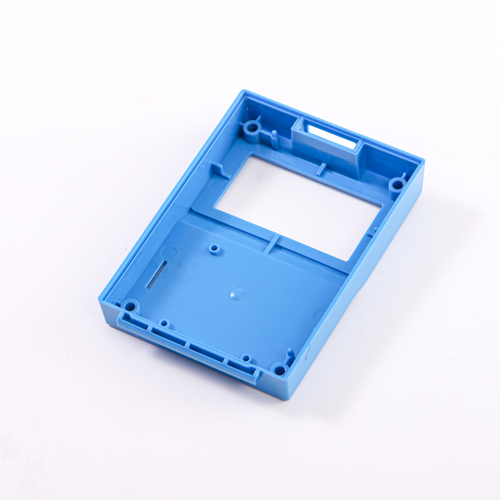
Multi-Cavity Injection Molding
The team specializes in looking for any potential problems with part geometry or tolerances that could lead to poor steel construction or require special tool functions such as lifters, sliders, and threads/dethreads. The physical and chemical properties of the selected resin were evaluated in order to select the appropriate die steel and evaluate the cooling effect of the die. In addition to determining the appropriate vent location, mold flow assessment is performed to determine the best gate type and gate location.
Manufacturability reviews include validation of standard plastic design practices and integration of mold details to create the most robust designs. Confirm the specifications and source of the tools and the source of the purchased parts. In addition, a comprehensive process failure mode impact analysis (FAILURE) was completed. Our company can also make molds for customers, low cost, high quality products. At the same time, we will provide services for the whole mold project development, including design, mold manufacturing, Plastic Parts production and after-sales service.
Multi-Cavity Injection Molding,Plastic Injection Molding Product,Multi-Cavity Design Plastic Injection Molding,Multi-Cavities Steel Injection Molding
Suzhou Dongye Precision Molding Co.,Ltd. , https://www.sjinjectionmolding.com